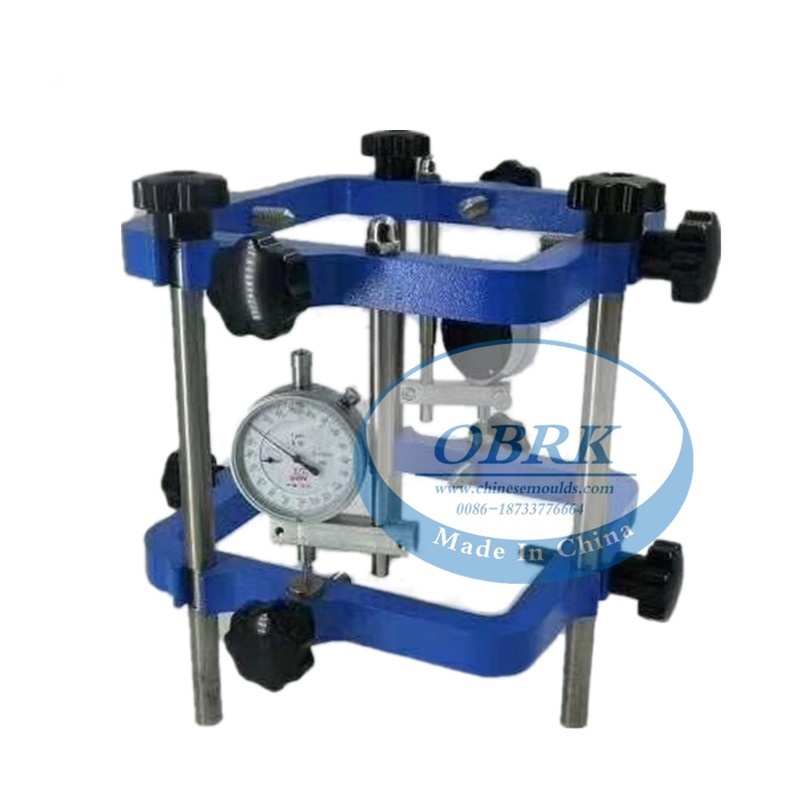

It is used for determining the axial deformation and diametrical extension of concrete cylinder specimens during the compression test. Complete with 2x0.001 mm dial gauge and wooden box.It is used to determine the strain and deformation characteristics of concrete and cylindrical specimens. It is comprises two lightweight metal castings for clamping to the specimens, two length gauge bars, a dial gauge 5 mm travel x 0.001 mm divisions. Compressometer for cylinder dia. 150 x 300, 160 x 320 mm. and 6” x 12”.
Product Name | Concrete Compressometer Apparatus |
Size of specimen | 150×150×300mm,100×100×300mm |
Measuring range of dial gauge | 0--1mm |
Central distance between upper and lower clamping rings | 150mm |
The ring from the bottom of the distance | 75mm |
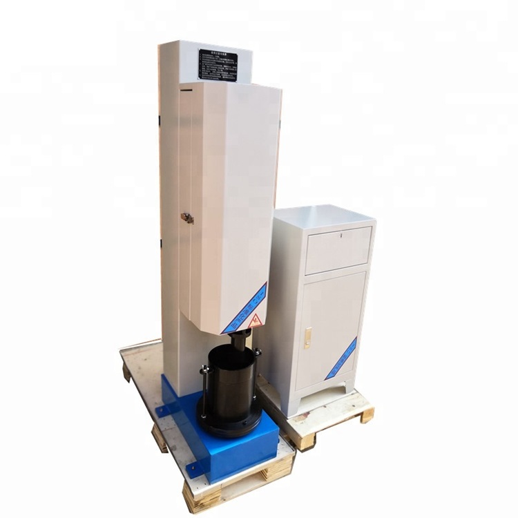
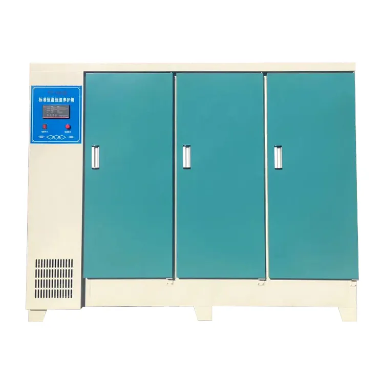
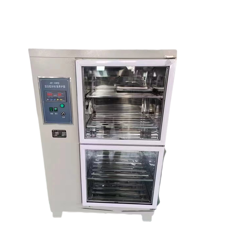
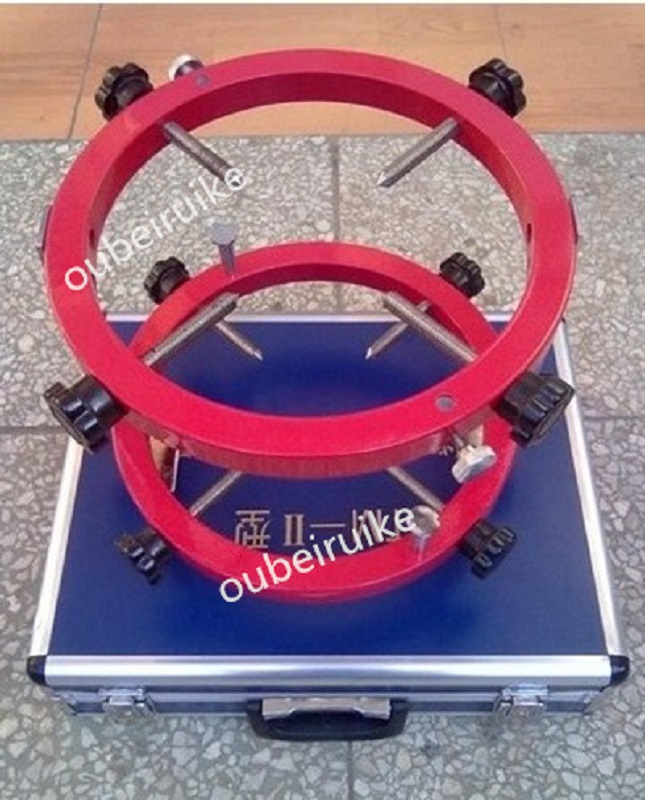
The concrete elastic modulus tester is developed and produced in accordance with the standards such as JTG-2005 "Highway Engineering Cement Concrete Test Procedures" and ASTMC-469. This instrument is mainly used for measuring the elastic modulus of concrete test blocks. The instrument is simple, lightweight, and convenient for use in experiments.
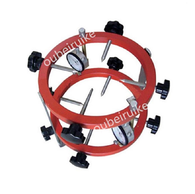
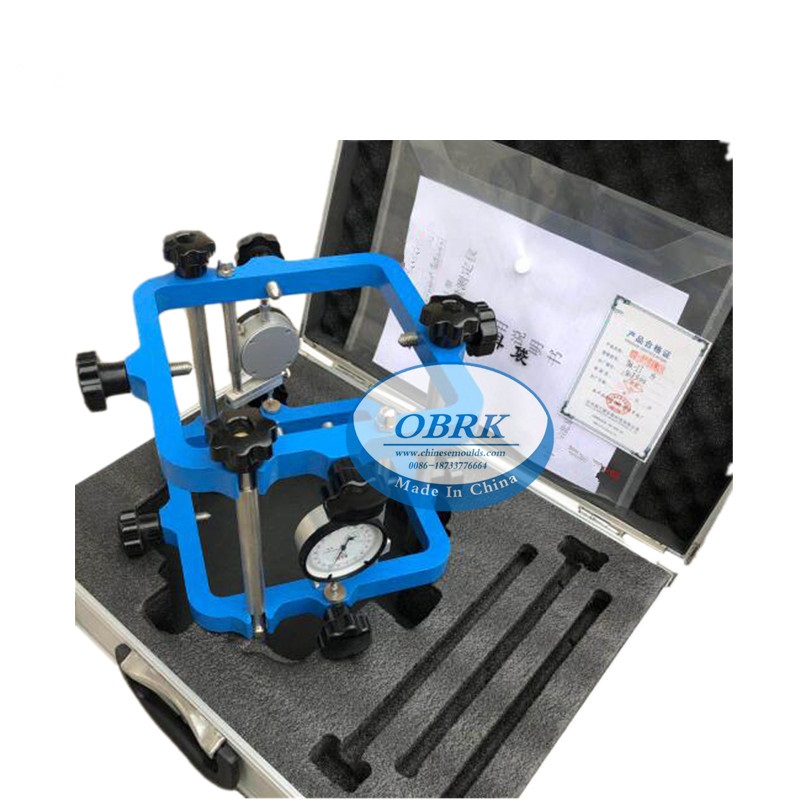
Instrument structure: This measuring instrument is composed of an upper ring, a lower ring, a contact rod, a micrometer and a locking screw.
Technical Specifications:
1. Applicable concrete modulus of elasticity test blocks... 150×150×300mm, φ150×300mm; 100×100×300mm, φ100×300mm
2. Micrometer range... 0-1mm
3. Center distance between the upper and lower rings... 150mm
4. Distance from the lower end of the ring......... 75mm
Method for using the concrete elastic modulus tester:
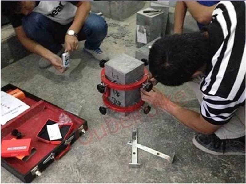
Before the test begins, place the elastic modulus measuring instrument on a flat surface, unscrew the locking screws of the test block, install the micrometer, loosen the locking screws of the fixed plate, remove the fixed plate, and then the measuring instrument will be positioned on the test block. Place the measuring instrument together with the test block on the lower pressing plate of the pressure testing machine, align the center of the test block with the center of the lower pressing plate of the pressure testing machine, and zero the micrometer.
Start the press machine. When the upper pressing plate is close to the specimen, adjust the ball seat to ensure balanced contact. Load the specimen continuously and uniformly at a speed of 0.2 - 0.3 MPa/s to 40% of the expected failure load Pa (that is, 40% of the expected failure load value of the specimen). Then unload it to zero at the same speed. Repeat this process three times. During the preloading, observe whether the press machine and the micrometer are functioning properly. The difference in deformation between the two sides of the specimen's micrometer should not exceed 15% of the average deformation value, and it should not be positive or negative in opposite directions. When using specimens with a 100mm × 100mm cross-section, the difference in deformation between the two sides should not exceed 20% of the average deformation value. Otherwise, gently tap the ball seat with hard wood to adjust it or change the position of the specimen. Perform the fourth loading at the same speed, starting at the initial load, starting at the initial load PO (approximately 0.5 MPa), maintaining for 30 seconds, reading the values of the micrometers on both sides △O, then load to PA and maintain for about 30 seconds, reading the values of the micrometers on both sides △A, respectively calculating the increment of deformation △A - △O, and calculating the average value, setting it as △4; after reading △A, unload to PO at the same speed, maintaining for about 30 seconds, reading the values of the micrometers on both sides △00, following the same steps, perform the fifth loading, and calculate △50
The difference between △5 and △4 should not exceed 0.0002 (L = 150mm). Otherwise, repeat the above steps until the difference between the deformation values of the two adjacent loadings meets the requirements. Take the last deformation value △0 as the standard. Then remove the micrometer and continue loading at the same speed until the specimen fails. Record the cyclic axial compressive strength Ra.
Calculation of test results: The compressive elastic modulus Ec of concrete is calculated according to the following formula:
PA - Final Load (N)
PO - Initial Load (N)
△a - Fifth or Last Load Application, on both sides of the specimen at PA and PO
Average deformation difference (mm)
L - gauge length (mm)
A - cross-sectional area of the specimen (mm²)
The measured value is the arithmetic mean of the experimental results of 3 specimens. If the average difference of any one of the core compressive strength values exceeds 20% of the average value, then EC is calculated based on the arithmetic mean of the experimental results of the other two specimens. If the results of the two specimens exceed the specified limit, the test is invalid. The result is accurate to 100 MPa.
Notes: During the test, handle with care and avoid impact during transportation to prevent affecting the test accuracy.
Contact: Alice Bai
Tel: +8618633093611
Phone:
E-mail: alice@chinesemoulds.com
Add: 12 Building Fengxiangyuan, Binhedajie, Xianxian, Cangzhou City, Hebei Province, 062250,China
E-mail: alice@chinesemoulds.com
WhatsApp: +86 186 3309 3611
Add: Xianxian, Cangzhou, Hebei, China