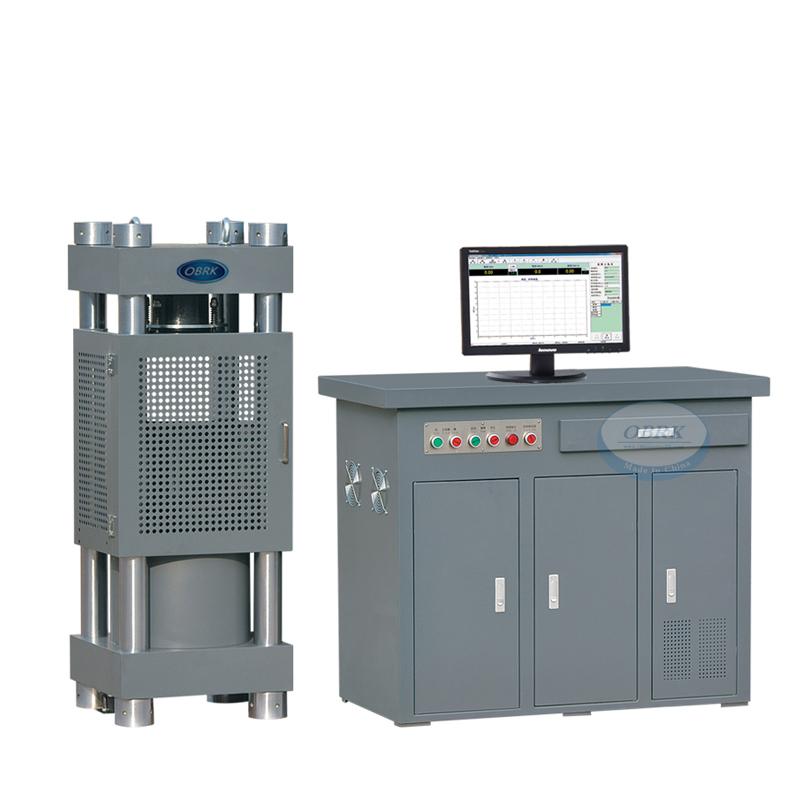
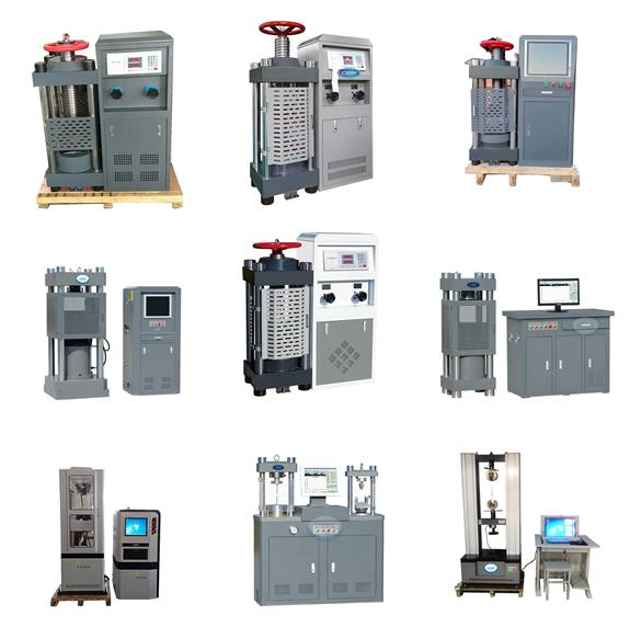
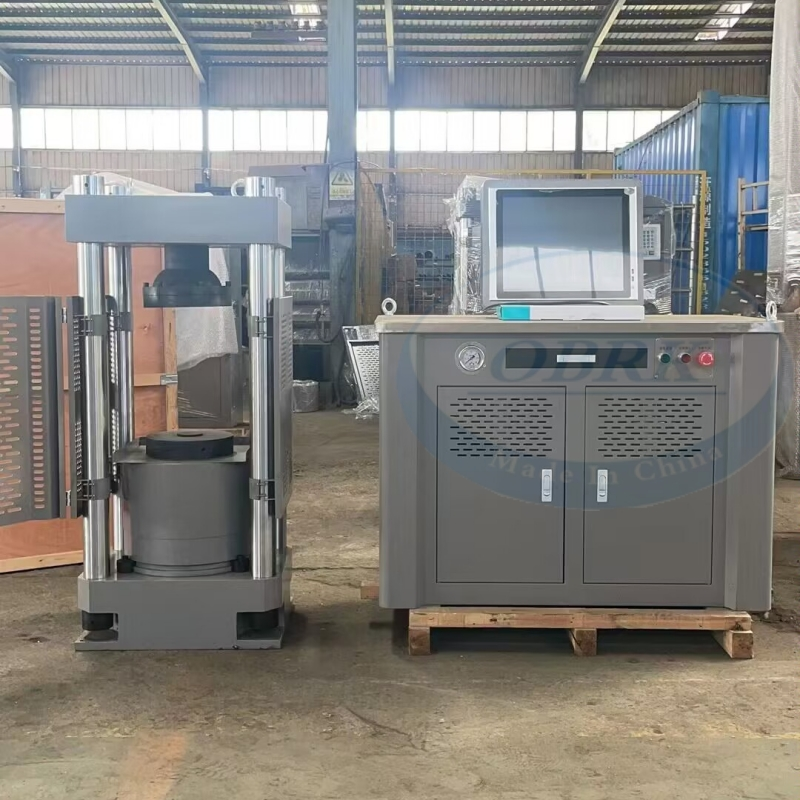
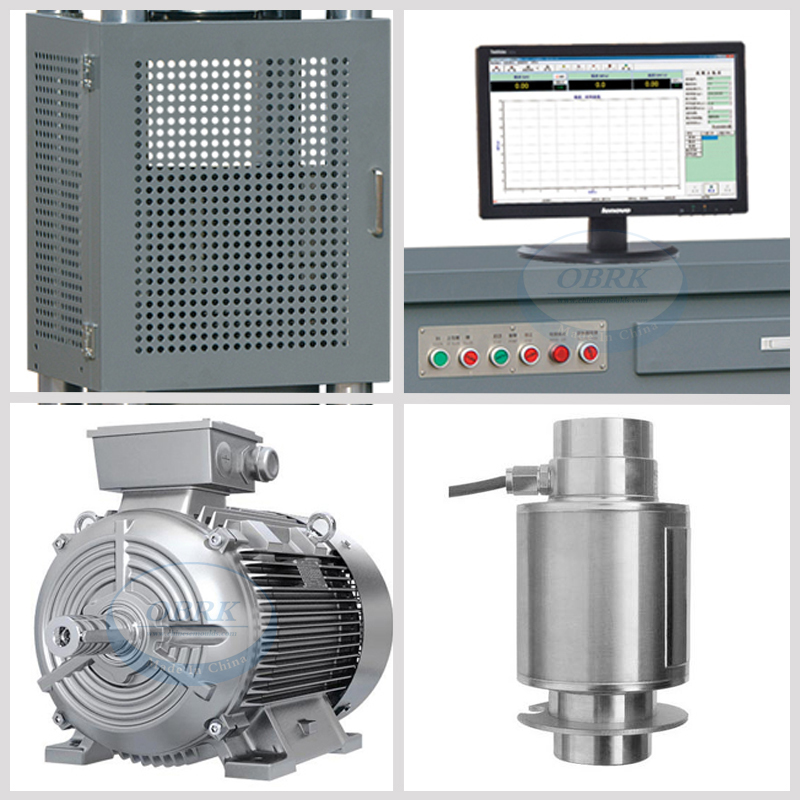
1. Precautions
Before installing and using this equipment, please read this manual carefully and keep it properly for future reference. Installation environment requirements
1. Ambient temperature: 10℃ to 35℃
2.The relative humidity shall not exceed 80%
3.In an environment free from vibration, corrosive media and strong electromagnetic field interference
4.The levelness should not exceed 0.2mm/1000mm
5.There should be a space of 0.7 meters around, and the equipment must be reliably grounded.
Power supply requirements
This device uses 230V . The voltage is stable and should not exceed ±10% of the rated voltage. The allowable current of the socket should not exceed 10A.
Requirements for hydraulic oil
This equipment uses standard hydraulic oil as the working fluid.
When the room temperature is above 25℃, use No. 68 anti-wear hydraulic oil.
When the room temperature is below 25℃, use No. 46 anti-wear hydraulic oil. When the room temperature is too low in winter, please warm up the machine (start the oil pump motor) for 10 minutes after turning it on before adding load. When used frequently, the hydraulic oil needs to be replaced every six months. Whether the oil tank and filter are cleaned or not depends on the degree of oil contamination.
This equipment cannot be replaced by engine oil, gasoline or other oil products. Faults of hydraulic components caused by improper use of oil will not be covered by the warranty.
Regarding emergency shutdown
In case of any emergency during installation, commissioning or operation, such as the solenoid valve not being released, abnormal operation of the motor, or problems with the test piece, which may damage the machine components or injure the test personnel, please immediately turn on the circuit breaker.
Accuracy
All the equipment has been precisely calibrated before leaving the factory. Please do not adjust the calibration parameters without authorization. Increased measurement errors caused by unauthorized adjustment of calibration parameters will not be covered by the warranty. You can contact the local quality supervision department for verification according to the precision grade indicated on the equipment.
Maximum force
Please determine the range of the equipment according to the factory nameplate. The range of the equipment has been adjusted at the factory. Do not modify the range parameters without authorization. Unauthorized modification of the range parameters may cause excessive output force of the equipment, damaging mechanical components, or insufficient output force, failing to reach the set value. Mechanical component damage caused by unauthorized adjustment of the range parameters will not be covered by the warranty.
2.Equipment Overview
The micro-electro-hydraulic servo pressure testing machine is a material developed and manufactured based on standards such as GB/T 17671 "Test Methods for Strength of Cement Mortar (ISO) Method", JC/T960-2005 "Automatic Pressure Testing Machine for Strength of Cement Mortar", and GB/T 50081-2019 "Standard Test Methods for Physical and Mechanical Properties of Concrete" Testing machine.
The HYE series micro-electro-hydraulic servo pressure testing machine is hydraulically loaded and uses electro-hydraulic servo control technology to test the mechanical properties of cement, mortar, brick, concrete and other building materials in terms of compressive and flexural strength. It displays the loading force value, loading speed and loading curve. The test data is automatically processed, stored and printed.
3. Technical parameters
3.1 Max load capacity: 2000KN
3.2Compression space: 360mm
3.3Travel of piston: 200mm
3.4Piston displacement velocity: 0-60mm/min
3.5Loading speed: 0.02%-2%FS/s
3.6Platen size: Φ300mm
3.7Effective distance between columns: 400×320mm
3.8Dimensions ( Body): 640×560x1500 mm
3.9Dimensions(control cabinet): 700×540×1500mm
3.10Power: 2.0KW
3.11Weight: 1500KG
4. Installation and commissioning
4.1Preparation of installation tools
Check the accessories randomly attached to the equipment according to the packing list provided randomly with the equipment to ensure that the corresponding accessories are complete.
Prepare a set of cross-head screwdrivers, adjustable wrenches and Allen wrenches
4.2Fixed mainframe
Refer to the foundation drawing and fix the equipment according to the foundation fixing parameters (for details, please refer to the parameters and explanations in the foundation drawing section of the appendix of this manual).
4.3 Oil line connection
Add an appropriate amount of hydraulic oil according to the markings on the oil tank installed inside the control cabinet. (After adding the hydraulic oil, the oil in the oil tank should be left to stand for at least 3 hours before the equipment is officially put into use to facilitate the self-discharge of air bubbles in the hydraulic oil.)
4.4 Electrical connection
Connect the power supply. Please connect the power supply strictly in accordance with the instructions on the power cord provided randomly. For the three-phase four-wire power cord, the neutral wire (Line 4) must not be connected incorrectly!
Open the package of the random printer and install the printer by yourself according to the installation instructions attached to the printer. After the printer is installed and connected to the computer, place it in a convenient location for operation (the printer driver is saved on the local disk of the random computer and needs to be installed by yourself).
4.5 First debugging and trial operation
After the electrical installation is completed, connect the power supply of the equipment, turn on the equipment switch, and run the equipment no-load in accordance with the operation requirements in the user manual. During the process of the oil cylinder piston rising (not exceeding the maximum stroke), observe whether there are any abnormal phenomena. If there are, unload and stop the machine for inspection and troubleshooting. If not, unloading causes the piston to descend to its original position and the equipment debugging is completed.
5.Usage method
5.1 Turn on the power switch on the control panel, open the protective net (be sure to remove the reinforcing objects between the upper and lower pressure plates before use), place the specimen at the geometric center position of the lower pressure plate plane (or arrange the specimen through the matching fixture), adjust the number of spacers under the lower pressure plate (please note that the positioning pins should be placed correctly when placing the spacers), and adjust the space for placing the specimen. Adjust the number of spacers to the extent that the upper pressure plate does not contact the angular contact specimen.
5.2 Turn on the oil pump start switch, power on the controller, turn on the industrial computer/computer, log in to the TESTMASTER testing machine measurement and control software to enter the control system, select the test method according to the test requirements, and set the parameters before the test (for the use of the control system, please refer to the "SuperTest Pressure Testing Machine Measurement and Control Software User Manual").
5.3 Close the protective net, reset the force value to zero, and then start the test operation. Click the run button on the software interface of the control system. When the lower pressure plate begins to rise but the upper surface of the specimen does not touch the upper pressure plate, press the reset button again to reset the force value, and the test will proceed automatically. For the use of the control system, please refer to the "SuperTest Pressure Testing Machine Measurement and Control Software User Manual".
5.4 After the test is completed, the data is automatically recorded in the control system. Set the printing content in the control system software and then print the data. For the printing setting method, please refer to the "User Manual of Testing Machine Control Software".
5.5 After the test is completed, restore the equipment to its initial state, exit the control system software, turn off the oil pump, power off the controller, shut down the computer, and turn off the main power supply. Wipe and clean the residues and debris on the equipment table and at the lead screw position in a timely manner to avoid affecting the transmission components of the equipment.
6.Daily maintenance
6.1Before each startup, check for any oil leakage (specific parts such as oil pipes, various control valves, oil tanks, etc.), whether the bolts (i.e., the general term for all screws) are tightened, and whether the electrical system is in good condition. Regularly inspect to maintain the integrity of its components.
6.2After each test, the piston should be lowered to the lowest position and the garbage should be cleaned up in time. The workbench should be treated for rust prevention.
6.3 Prevent the instrument from being eroded by high temperature, excessive humidity, dust, corrosive media, water, etc.
6.4The hydraulic oil must be replaced annually or after a cumulative operation of 2,000 hours.
6.5Do not install other application software in the computer to avoid the control system software of the testing machine not operating normally. Computers should be prevented from being infected by viruses.
6.6At no time should power lines or signal lines be unplugged or unplugged while powered on; otherwise, it is very easy to damage the control components.
6.7During the test, please do not press the buttons on the control cabinet panel, operation box or test software at will.
6.8During the experiment, do not touch the equipment and various connecting wires at will to avoid affecting the accuracy of the data.
6.9 Regularly check the changes in the fuel tank level.
6.10 Regularly check whether the connection wires of the controller are in good contact. If any are loose, they should be tightened in time.
6.11If the equipment is not to be used for a long time after the test, turn off the main power supply of the equipment.
6.12This equipment is a precision measuring device. It should be operated by designated personnel, machines and positions. Untrained non-operators are strictly prohibited from operating it.
7.Appendix
8.Troubleshooting
Phenomenon | Reason | Inspection and Elimination |
The screen doesn't light up. | 1.The power supply is not powered on 2. The fuse on the digital display meter is damaged | Please have a professional electrician check the power supply 2. Check if there is a short circuit in the circuit. If there is no short circuit, replace the fuse |
The controller cannot be connected. | 1. Abnormal power-on of the controller 2. Poor contact of the serial port connection 3. The serial port of the computer is damaged 4. The serial port of the controller is damaged | 1.Restart the controller 2. Reconnect 3. Repair the serial port of the computer host 4. Replace the controller |
The oil pump doesn't start. | 1.The voltage is abnormal 2. The oil pump motor is short-circuited and damaged 3. The controller has no output voltag | 1.Please have a professional electrician check the power supply 2. Replace the oil pump motor 3. Replace the controller |
Powerless value display | 1.The connection of the pressure sensor has come loose 2. The controller is damaged 3. The pressure sensor is damaged | 1.Reconnect 2. Replace the controller 3. Replace the pressure sensor |
The value of the applied pressure remains unchanged | 1.The controller crashed 2. Poor contact of the sensing wire 3. There is A problem with the A/D sampling of the controller | 1.Restart the controller 2. Reconnect 3. Please contact the manufacturer for repair |
The full scale cannot be reached | 1.The hydraulic oil is not filled up 2. Oil is seeping from the pipe joints 3. The digital valve is leaking oil or getting stuck | 1.Fill up the hydraulic oil 2. Tighten the pipe joints 3. Replace the digital valve |
Oil leakage at the piston | 1.The machine was not placed stably and the piston was too low on the side 2. The sealing ring is damaged | 1. Level the equipment as required 2. Replace the sealing ring |
There is abnormal noise from the oil pump | The connecting screw between the oil pump and the motor is loose | Tighten the screw |
The piston doesn't rise. | 1.The initial opening degree of the valve port is too small 2. The digital valve is stuck 3. The pressure reducing valve is stuck | 1.Adjust the initial opening degree of the valve port 2. Replace the digital valve 3. Replace the pressure reducing valve |
The piston rises too fast | 1.The initial opening degree of the valve port is too large 2. The digital valve is stuck | 1.Reduce the initial opening degree of the digital valve 2. Replace the digital valve |
Contact: Alice Bai
Tel: +8618633093611
Phone:
E-mail: Alice@chinesemoulds.com
Add: 12 Building Fengxiangyuan, Binhedajie, Xianxian, Cangzhou City, Hebei Province, 062250,China